
Rally Car Streaming Prototype
A record-first video streaming prototype for rally, rally raid and off-road cars on the Rockchip RK3588. Hardware HEVC recording to NVMe, SRT live streaming, chunked upload over several uplinks and two in-car units, built in short phases and field tested on a road test and an off-road event with almost no coverage.
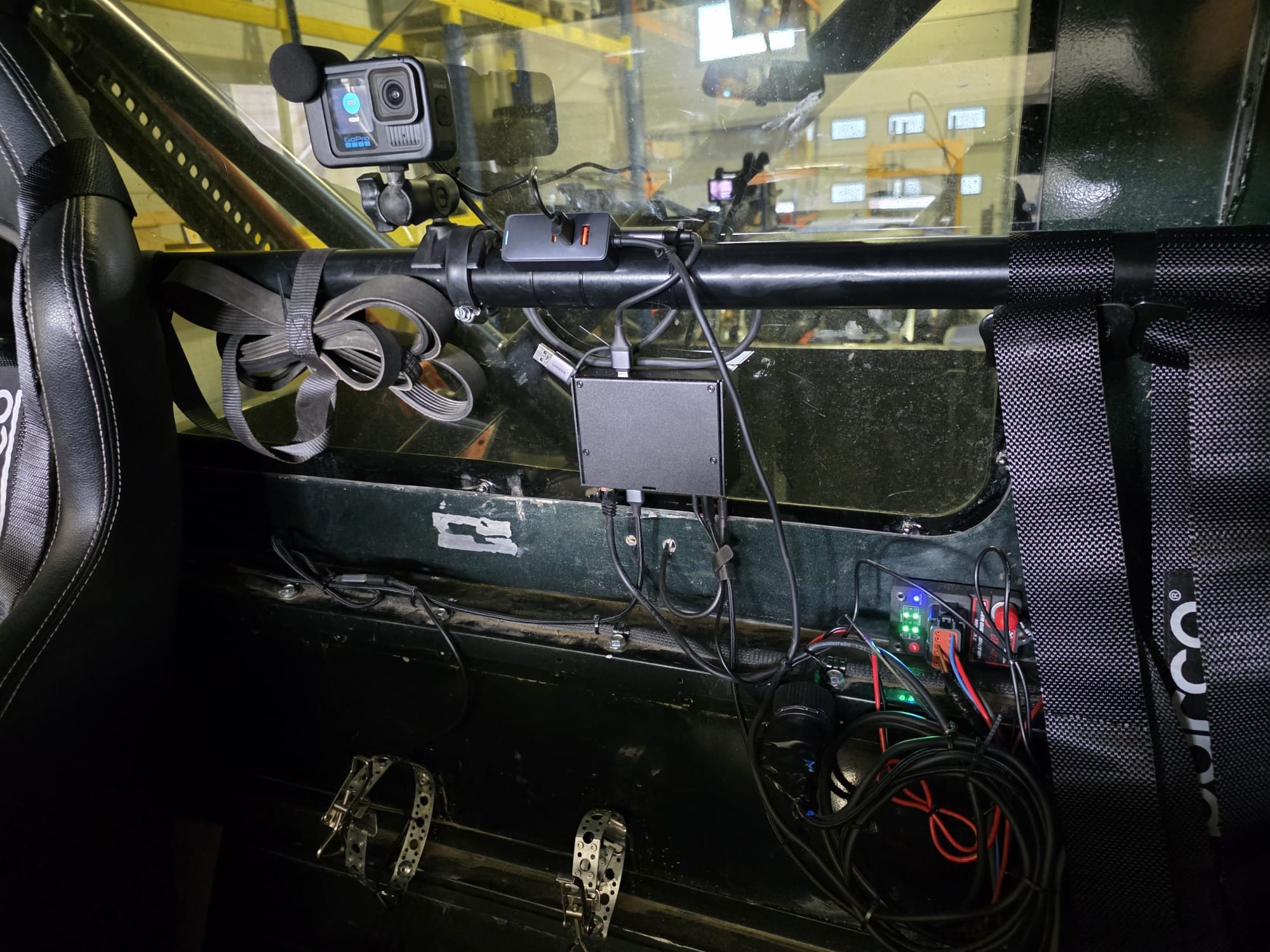
The founder of a European motorsport video startup came to me in October 2025. His company builds video tools for rally, rally raid, off-road and circuit racing, and he had tested most of the streaming gear on the market and found none of it made for a race car. A few weeks later a box of that gear arrived (cellular streaming encoders, spare modems, action cameras, converters) with a note saying I could take anything apart.
The gap he had found
That gear is made for a camera operator at the side of a field. In a car, nothing he had tried would store and forward, so footage shot while coverage was down was lost, and the units were expensive, fiddly to set up and not IP rated.
The car makes it harder. A rally raid stage runs one to four hours, and a car can be out of coverage for twenty minutes at a time. Cabin temperatures of 50 to 70 °C are realistic, past the 40 °C rating of most M.2 capture cards. Ignition coils and injector drivers make the electrical environment noisy, and nobody wants open vents in a competition car. He wanted a box that records first, rides through bad coverage, sets up quickly in the paddock and is priced for teams and organisers.
Phases
Phase 1: Architecture (October 2025)
A week of paper work covering the capture to delivery pipeline, a hardware shortlist, the power and thermal concept, a risk register and a bench test plan.
Phase 2: Bench prototype and MVP (late October to early December 2025)
Multi-camera capture, recording and streaming in parallel, chunked upload, cloud playback and dashboards, all on real hardware.
Phase 2.5: Two in-car units (December 2025 to January 2026)
Two compact units for the car, a quick start guide and a flashable image so the client could build more himself.
Field support (January and April 2026)
Log analysis and remote fixes around a road test and an off-road navigation event in Central Europe.
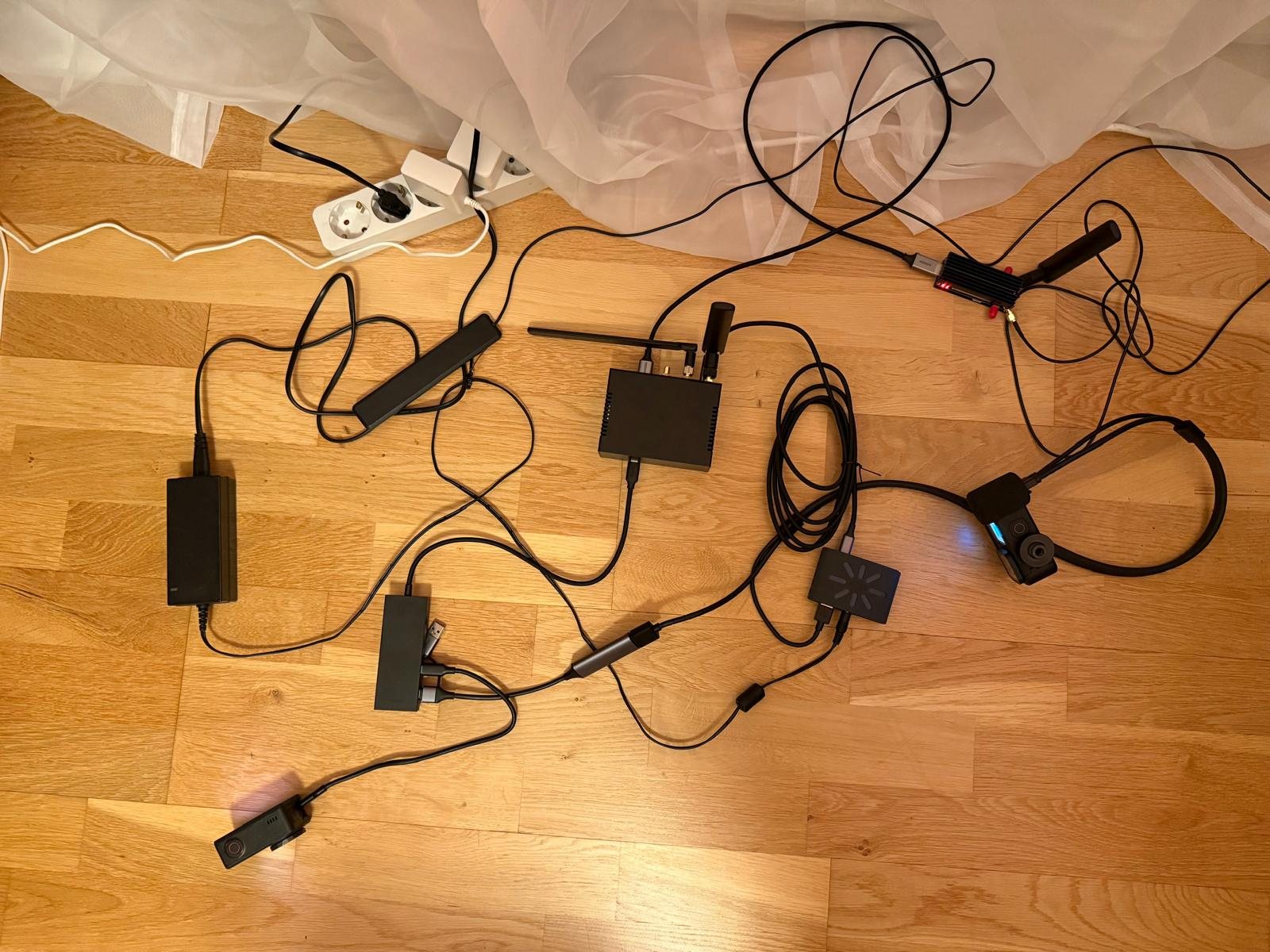 Phase 2 bench setup: compute with its antennas, an LTE modem on a USB M.2 adapter, a capture dongle and two action cameras, all on USB.
Decisions
Recording first
Store and forward was the missing piece, so recording came first. In Live mode each camera’s video is decoded or converted to raw NV12 once and split with a tee. One branch feeds the RK3588’s hardware HEVC encoder and a Matroska file on the NVMe, which stays playable up to wherever a crash or power cut stopped it. The other is encoded in software for the stream behind a leaky queue, so a stalled uplink sheds stream frames without backing up into the file writer.
Two stream modes
In late November the founder described what rally raid should look like to a viewer. The picture freezes when the car drops out, and once it is back the missing part fills in behind the live stream. A single live pipeline with a fixed bitrate cap can’t do that, so I proposed separate Live and Buffered modes and he kept both.
Board and scope
The edge unit is a Radxa ROCK 5B+ on the RK3588, a board I knew from a handheld product, with native HDMI input, NVMe and hardware HEVC encoding. A Jetson would only have made sense with CUDA-heavy AI on board, and the founder cut edge AI from the Phase 2 options within half an hour, along with RIST, because neither would set the product apart yet. He asked for OBD-II and GPS instead, since vehicle data puts the product up against premium motorsport video and data systems. He also settled on 1080p for phone viewers and at most two cameras per car, and we skipped a custom PCB to move faster.
The stack
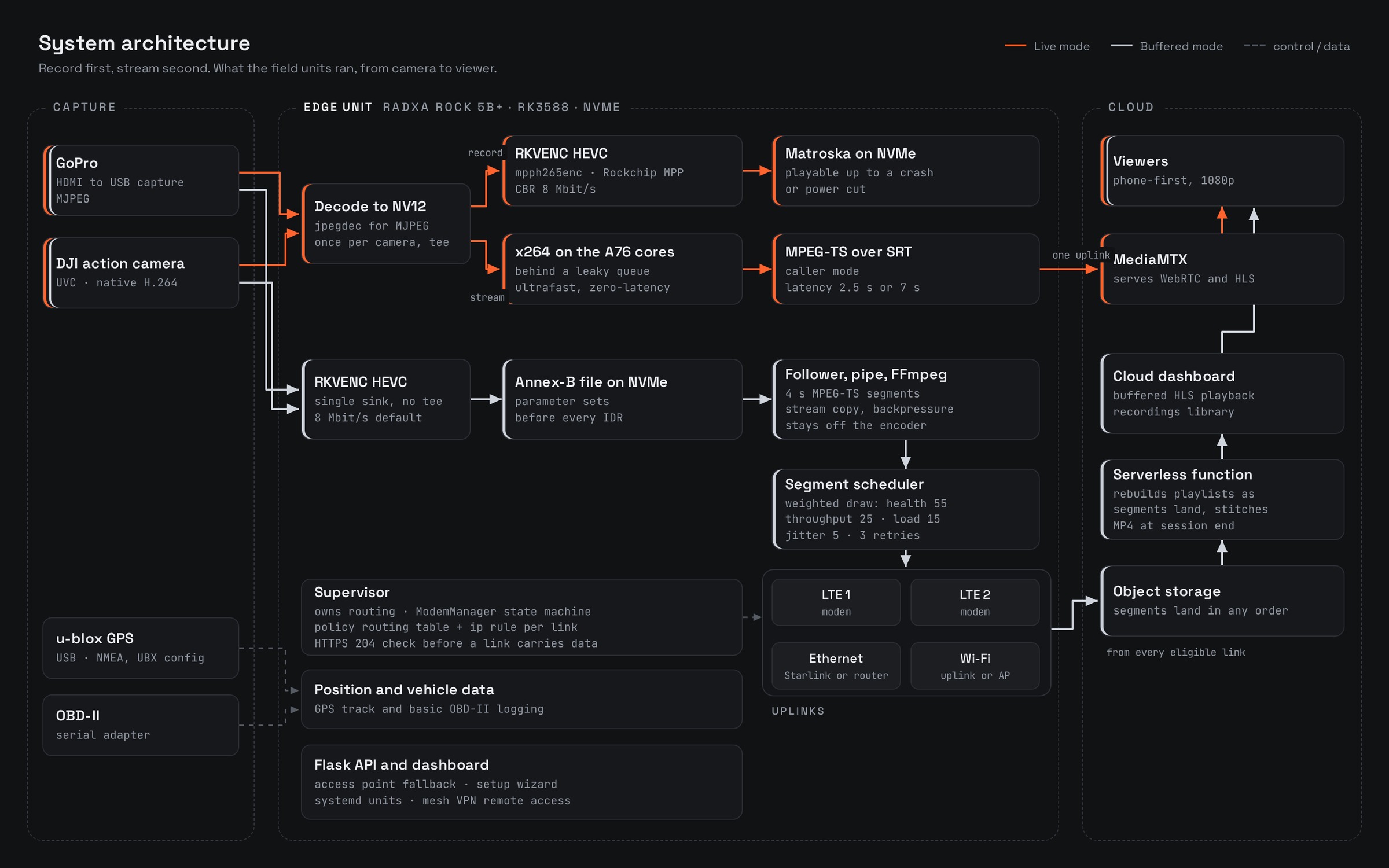 How the field units moved video from camera to viewer. Live mode in orange, Buffered mode in grey. Open full size.
Compute and encode
Radxa ROCK 5B+, RK3588 with four A76 and four A55 cores. Two RKVENC encoder cores driven through Rockchip MPP.
Capture
GoPros through USB HDMI capture dongles (MJPEG), a DJI action camera over UVC (native H.264), generic UVC webcams.
Recording
Hardware HEVC through mpph265enc, CBR, 8 Mbit/s and a 60-frame GOP in the default config. Matroska in Live mode, raw Annex-B HEVC plus AAC in Buffered mode, all on NVMe.
Live transport
Software H.264 stream encode with x264enc, MPEG-TS over SRT in caller mode. Latency profiles of 2.5 s with a 45-frame GOP or 7 s with a 60-frame GOP. MediaMTX in the cloud serving WebRTC and HLS.
Buffered transport
4 s MPEG-TS HLS segments cut by FFmpeg with stream copy, one uploader per uplink, playlists rebuilt by a serverless function as segments land.
Connectivity
Two LTE modems per field unit under ModemManager, Wi-Fi, Ethernet for a Starlink terminal or router. One supervisor owns routing, with a policy routing table per modem.
Position and vehicle data
USB u-blox receiver over NMEA, configured over UBX. Basic OBD-II logging through a serial adapter.
Platform
Ubuntu, systemd units, Flask API and dashboards, SD card image with first-boot provisioning, git-based updates, mesh VPN for remote access.
Capture and encoding
I started the software on a Raspberry Pi 5 while the boards were in transit, and by early November one-second H.264 chunks from a DJI action camera were going from the RK3588 to the cloud.
The GoPros took longer. With HDMI connected, one would boot-loop on every supply I tried until it shared a ground path with the rest of the system. The USB capture dongles I found all deliver the GoPro’s uncompressed HDMI as MJPEG or YUYV, never H.264 or H.265, and MJPEG needs a software decode (jpegdec) and a conversion to NV12 before the encoder will take it. An early measurement had two 1080p60 GoPro streams recording at about 50% CPU, with the natively H.264 DJI adding only 5 to 10%. Holding full-quality GoPro capture after that took a stretch of driver and library work on the Rockchip platform.
The board’s own HDMI receiver shows up in camera discovery, but the pipelines never got a branch for it, so every camera in the field came in over USB. USB enumeration once put a webcam on the device node meant for a GoPro dongle, so cameras are now resolved by udev port path, then VID:PID, then card name.
Live mode
The live stream is encoded with x264 (ultrafast, zero-latency tune, baseline profile) on the A76 cores. That leaves both hardware encoder cores to recording and lets bitrate and resolution change without restarting the pipeline. The default SRT latency is 2.5 s, with a 7 s profile for links that are bad but still up.
The code carries an adaptive controller for this. Every five seconds it scores each stream from 0 to 1, weighting the RTT trend as the cloud side reports it at 50%, the retransmission ratio at 30% and packet loss at 15%, and the average picks one of four tiers, with priority cameras holding resolution longest. On the bench in late November the stream stepped its resolution and bitrate down as the uplink failed, but I don’t have field data showing the controller at work. Before recording was added, the bench live stream held up to about 10% packet loss.
Buffered mode
Here each camera gets a single-sink GStreamer pipeline with no tee and no muxer, encoding HEVC (8 Mbit/s by default) into a raw Annex-B file on the NVMe with parameter sets repeated before every IDR. A small file follower tails each growing file into a named pipe, and FFmpeg cuts 4 s MPEG-TS segments from it by stream copy (fragmented MP4 from two live pipes had timestamp ordering problems). If FFmpeg or the uploader falls behind, the pipe blocks and the encoder keeps writing to disk. Keeping that backpressure off the encoder is what stopped the VPU and DMA memory crashes of the earlier Buffered mode design.
Each uplink gets its own uploader with an HTTP connection pool bound to that interface’s source address, and each modem has its own routing table and an ip rule for its current address, so traffic bound to a modem leaves through it whatever the default route does. A scheduler picks a link for each segment by weighted random draw over the supervisor’s health score (55%), EWMA upload throughput (25%), current load (15%) and upload-time jitter (5%). Every consecutive failure cuts a link’s score by a fifth, three in a row take it out for 10 s, and a failed segment gets up to three retries.
In the cloud a serverless function rebuilds the playlists from whatever has landed in object storage, so segments that arrive late after a coverage gap fall into place, and a full MP4 is stitched when the session ends.
Connectivity
The plan paired a Cat 16 LTE-A main modem with a Cat 6 second modem, with a 5G module and a RedCap part (the founder’s suggestion) as options. The field units ended up with two modems each, taken out of the commercial encoders he had sent me. The modems’ built-in GNSS wasn’t reliable, and a USB u-blox receiver took over position.
Each modem runs a state machine on top of ModemManager. RSRP below -110 dBm or SINR below 2 dB for 30 s marks it degraded, and a modem that has been degraded for more than two minutes and still reads RSRP below -118 dBm is faulted and backs off before going back through SIM check and attach.
A link carries uploads once an HTTPS check sent over that link gets a 204 response, with ping as the fallback. The default route is harder to get. A new link waits at metric 900 until it passes three checks over 30 s, so an Ethernet cable into a router with no internet can’t take the route away from the remote access session. In the field, NetworkManager’s autoconnect raced the supervisor for the same profiles, and I made the supervisor their only owner.
The hardware
Engineering testbed
A large 3D-printed box, about 250 × 200 × 50 mm, with a PWM fan, an internal air sensor, several modems and capture modules, for thermal and hot-swap testing in the lab.
Two field units
The same ROCK 5B+ in an off-the-shelf metal enclosure, which was the founder’s proposal. NVMe, two LTE modems, Wi-Fi, Ethernet for an external modem or a Starlink terminal, and USB GPS, powered from the car through a DC-DC converter.
Dashboards and cloud
An on-device dashboard that falls back to access point mode, and a cloud dashboard with a recordings library.
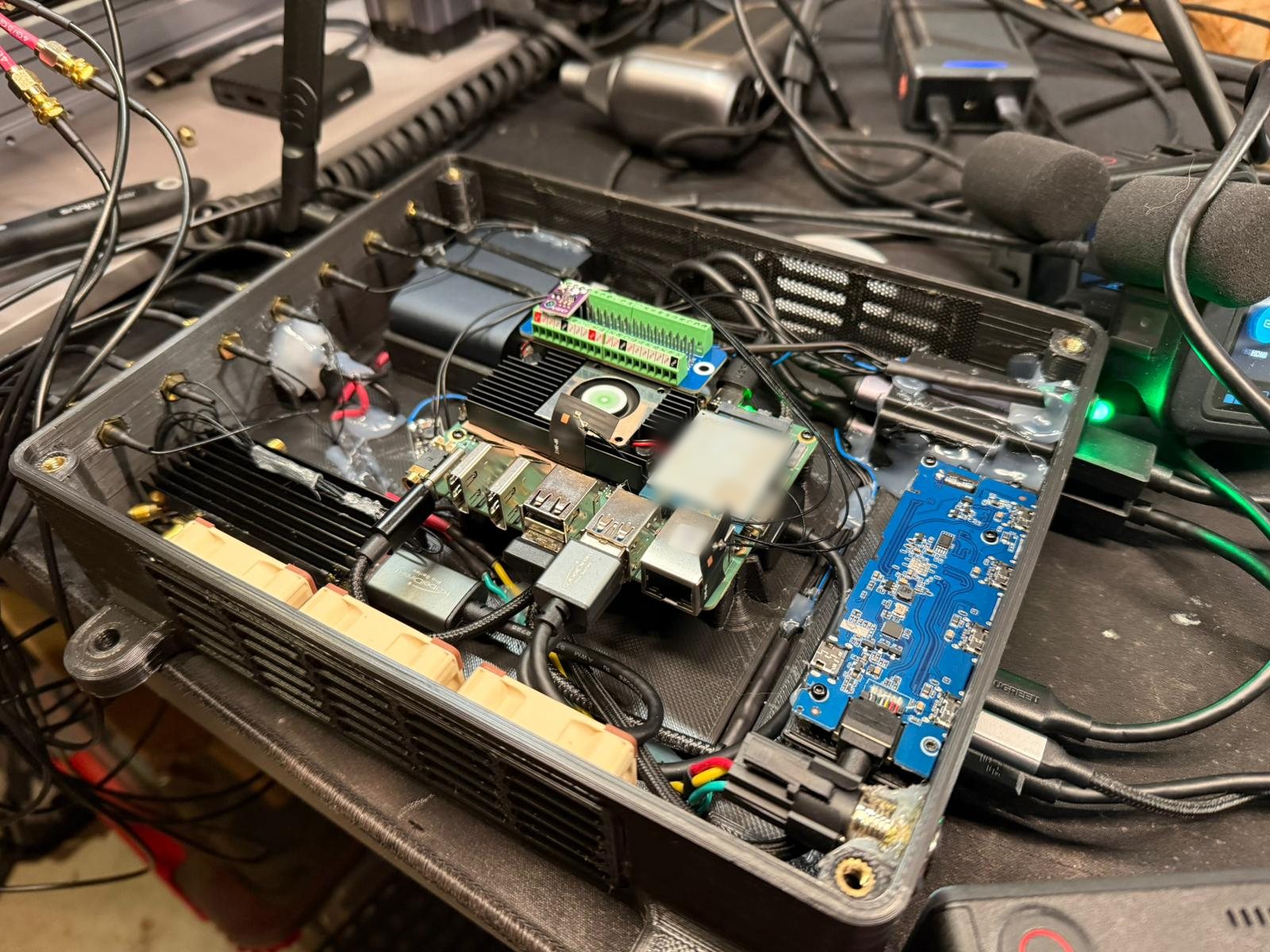 Inside the engineering testbed: the ROCK 5B+ under its fan cooler, an LTE modem, a terminal board carrying the air sensor, fans along the vented wall and SMA pigtails out to the antennas.
I had built the testbed big enough for every module we might try, and the founder was right that drivers would far more readily accept something the size of the bare board. Most of the work in that phase went into the SD card image. A clone regenerates its identity on first boot, prepares the NVMe, finds whatever cameras and modems are fitted and starts a setup wizard on its access point, so he could set up more units himself.
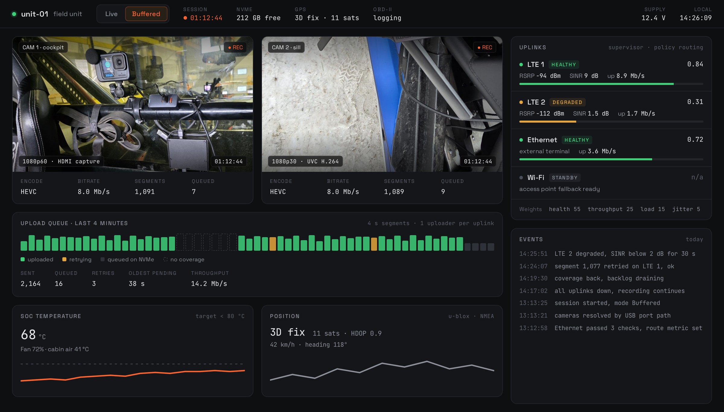 The on-device dashboard, redrawn as a mockup for this page: camera tiles, stream mode, upload queue, uplink health and thermals. Values are illustrative.
Thermal and power
With the stock cooler the testbed board ran about 40 °C above ambient at roughly 30 W while streaming, including powering both GoPros and charging the DJI. In a 50 to 70 °C cabin that rise puts the board past the 80 °C target. Proper thermal mass and a decent fan were estimated to cut the rise to 10 to 20 °C. The founder had asked early on whether passive cooling could work in a closed cabin, and the numbers said it can’t on its own. His idea of a replaceable external fan blowing across aluminium fins, ducted if needed so the heat leaves the cabin, became the agreed direction for a production enclosure.
For production we agreed on screw-locking USB and HDMI, easily replaced breakout cables (his idea), a motorsport power connector and a shielded custom board in a grounded metal housing.
Limits we found
The RK3588 datasheet is optimistic about encoding. In practice you can count on three to four reliable H.265 channels whatever capture inputs or M.2 capture cards you add, which is why the professional encoders we looked into pair an HDMI receiver and an FPGA with a dedicated encoder ASIC. Replicating that is a large custom hardware project.
For bonding we took the founder’s suggestion of sending each chunk over its own connection. That spreads Buffered mode across every eligible link, but a live SRT stream still leaves through one. True bonding (MPTCP-based, Speedify-class or custom) would be a big project of its own at broadcast quality, and I recommended testing it against the chunked approach first.
In the field
The first real test was a road test in January 2026. On a 40 minute drive in Live mode, a GoPro at 60 fps and 5 Mbit/s over SRT rode through small packet losses, dropped three times and picked up again after a refresh on the server. At the test site, where coverage was poor, the founder switched to Buffered mode, which worked as intended, though the conditions made it hard to judge. Modems and antennas caused most of the day’s trouble, and the modems were slow to come back after antenna swaps. He found the recordings library very handy, and it worked for him where a competing product had not.
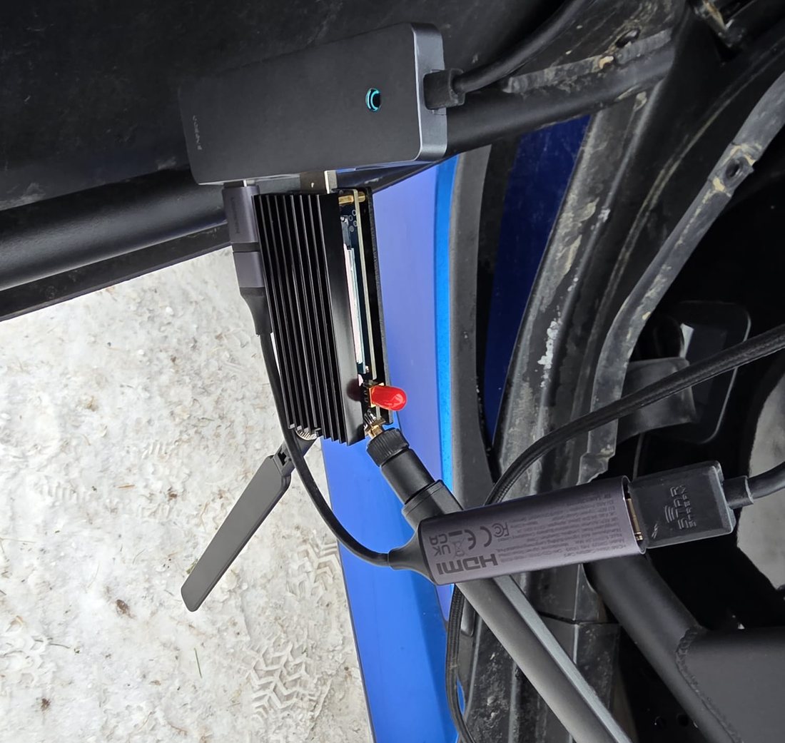
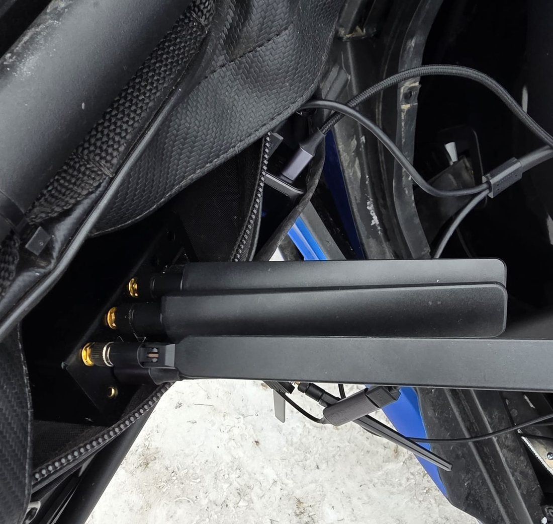 In the car: an LTE modem on its M.2 adapter and heatsink beside an HDMI capture dongle, and the antenna array on a field unit.
In April 2026 he sent a car to an off-road navigation event in Central Europe, slow driving through hills and forest. The evening before, he power cycled units and swapped cables while I worked on them over remote access until the upload path behaved. On race day the car had almost no cellular coverage and the Starlink terminal was blocked by trees. Buffered mode worked across multiple bitrates over whatever signal there was, with some segments missing and a few sessions timing out, which the founder considered fine for a prototype.
What the client took forward
The prototype showed that the architecture works in real conditions, and it showed where the software breaks on a bad connection. The code was written for speed, and we both knew it wasn’t production code. After the off-road event he concluded that production software should flip the control model, with the cloud commanding devices by push and confirm so nobody babysits commands over a weak link. I agree with him. He had also refocused the product on fleets of cars run by event organisers, and he has taken what we learned to a separate hardware partner who owns the production build.
Several of the best calls were his. Many of the most useful results were limits of the platform, like proper bonding or passive cooling in a closed cabin, and we found them on a prototype before any production money went into the step from hardware prototype to production.
Building a connected device that has to work with poor coverage, heat and vibration?
I can help you find its limits on a prototype, before you commit to production hardware.
Start a conversation